Signal Integrity Simulation
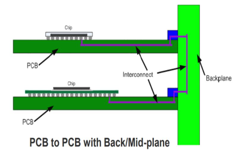
Simulation testing plays a crucial role in verifying the feasibility of a design before the physical development phase of a product, avoiding unnecessary errors. Engineers can simulate and evaluate the performance design of PCB circuit boards by using specialized software to analyze and predict their electrical and electromagnetic behavior.

iFlytek provides two main circuit board simulation analysis and testing services:


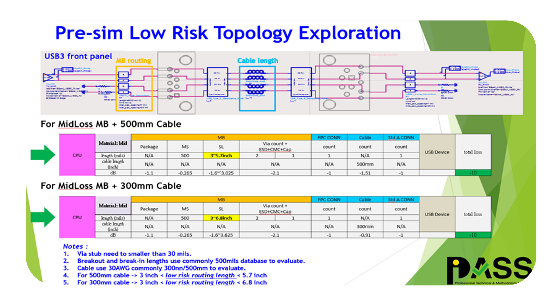
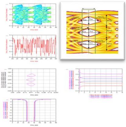
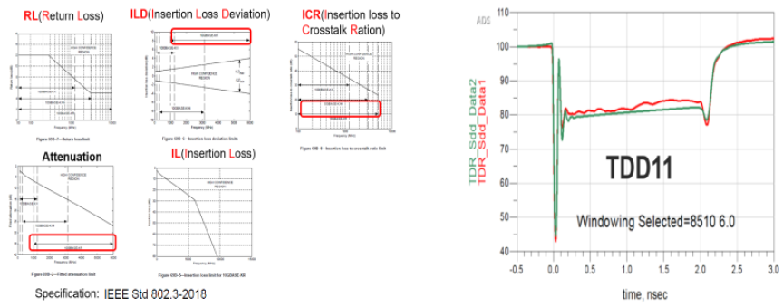
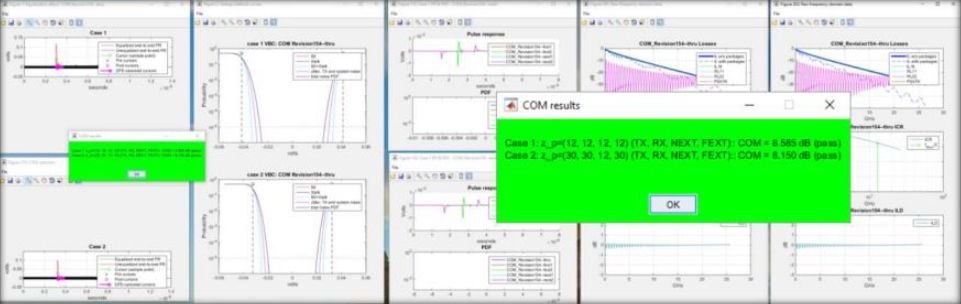
  • Signal Integrity Analysis and Testing: Customers can analyze and optimize signal integrity by simulating the transmission and reception of high-speed signals on circuit boards and their components. This includes evaluating signal reflection, crosstalk, impedance matching, and eye diagram analysis to confirm reliable data transmission and minimize signal degradation.
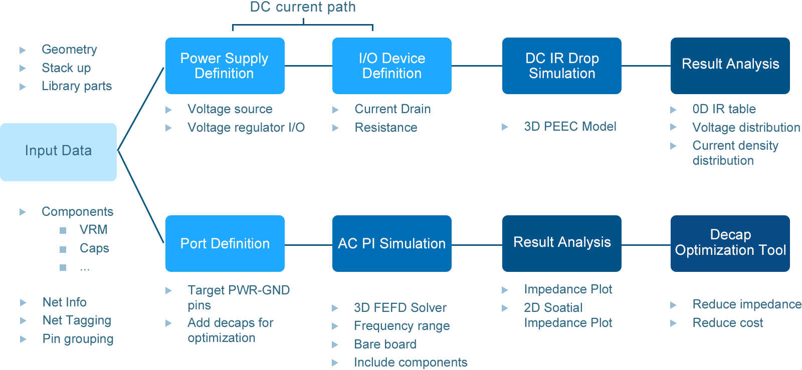
  • Power integrity analysis test: Analysis of the power distribution network confirms stable and noise-free power delivery to different components on the circuit board and helps identify potential voltage drops, ground bounce, and excessive noise. It can optimize power surface design, decoupling capacitor placement, and power supply routing.


In addition, the team members of iFlytek Technology have more than 20 years of experience in simulation testing, possess excellent testing skills, and can identify problems for customers in the early stages of product simulation and provide professional advice to save time and money and make the project run more smoothly.


iPasslabs|Simulation Item

Product High Speed Interface
Switch •800G/400G/100G/25G Ethernet
Server/Datacenter •PCIe1.0/2.0/3.0/4.0/5.0/6.0 •NVLink •CXL
Desktop/PC •DDR5, LPDDR5/5x, GDDR6/6x •USB4, USB Type A/C •Thunderbolt 5
Notebook/Laptop •HDMI 2.1, •DisplayPort 2.1, eDisplayPort •NVMe
Mobile/Storage •MIPI CSI/DSI D-PHY/C-PHY •MIPI UFS M-PHY •eMMC
Automotive •MIPI A-PHY •1000/100Base-T1, 10Base-T1S, 2.5/5/10Base-T1
Channel Quality Analysis
ØPre-Sim •PCB material loss evaluation •Routing topology evaluation •Channel crosstalk analysis •Design recommendation ØPost-Sim •S-parameter •Eye-diagram •TDR(Time Domain Reflectometry) •COM(Channel Operation Margin)
Category Item Descriptions
PI DC IR-drop Voltage drop analysis
DC Resistance DC Resistance analysis
AC Impedance Target Impedance performance analysis
400G/100G/25G Ethernet
PCIE Gen 1/2/3/4/5
DDR3/4/5, LPDDR3/4/5, GDDR4/5/6, eMMC5.0/5.1,
HOURS 1/2/3
AND HOURS 1/2/3 Channel quality analysis(Eye diagram、loss、impedance or crosstalk )
1000/100Base-T1, 10Base-T1S
HDMI 1.4/2/2.1, DisplayPort 1.4/2.0
USB 2.0/3.0/3.1 Gen1/2
Audio Codec

Simulation Tools

PathWaveADS

Simulation Capability|Pre-Simulation

Pre-Simulation

  • PCB material loss evaluation
  • Routing topology evaluation
  • Channel crosstalk analysis
  • Design recommendation

Post-Simulation

Eye diagram (NRZ & PAM4)

Post-Layout Analyses: PI workflow

Pre-Simulation

  • Evaluation of composite panels and selection of different number of layers
  • High-speed topology selection and system feasibility assessment
  • High-speed chip layout planning and trace length evaluation
  • High-speed signal routing/via impedance matching and fan-out optimization
  • Evaluation of I/O drive strength and termination resistor pairing strategies
  • Develop appropriate routing layout constraints for different high-speed signal interfaces.

Pre-Simulation

  • High-speed signal layout violation checks (layout rule check)
  • Compliance check before high-speed signal generation drawings are produced.